circuit diagram
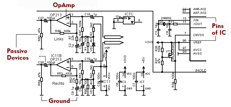
An electronic circuit diagram is a graphical representation on which the electronic components, processors, chips and modules are electrically connected to each other via connecting lines. Each individual passive and active component is represented by its own circuit symbol, integrated circuits and modules are identified by their connection points.
There are also fixed symbols for the supply voltages, which are entered in the circuit diagram in their level and polarity, for ground and earth, for the connection-free crossing of two conductors, as well as for the soldering point with which two or more leads are connected together. Circuit symbols are specified in IEC standard IEC 60617 and ANSI standard Y32, but some circuit symbols differ slightly. In general, circuit diagrams have certain degrees of freedom in their design and do not necessarily adhere to the IEC and ANSI recommendations.
If the circuit diagram complexity is very high, the individual components are replaced by functional assemblies. For example, a discrete amplifier is replaced by the amplifier symbol.
Circuit diagrams form the basis for PCB production. They are entered into a database together with the parts list and used for ordering and assembling PCBs.