coupling resistance
In connection with the demand for fully shielded cabling systems, the question of suitable evaluation criteria for shielding inevitably arises. The characteristic values for shielding are the coverage and the shielding factor.
Since shielding can have very different properties, the RF coupling resistance, the transfer impedance or the shielding effectiveness for cables have been defined in the responsible standardization committees. The coupling resistance is a measure of the quality of the shielding and is defined as the ratio of the voltage along the shield of the disturbed system to the current of the disturbing system. The limits are not yet specified in the draft standards, but should not exceed 50 milli-ohms per meter (mOhm/m) at 1 MHz and 100 milli-ohms/m at 10 MHz.
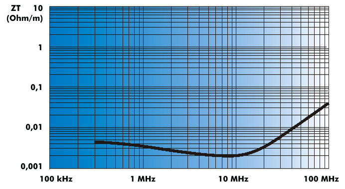
The magnitude and frequency response of the coupling resistance depend primarily on the structure of the shielding. At DC and low frequencies, the transfer impedance is identical to the DC resistance of the shielding. At increasing frequencies, it behaves completely differently, depending on its nature. For shielded balanced cables, the shielding attenuation can only be reasonably determined by measurement. There are several different measuring methods, which differ in the frequency range to be measured.