hollow waveguide
The transmission of high- frequency signals via metallic cables is limited by the skin effect. Up to frequencies in the microwave range, coaxial cables and microstrips are used, but these are subject to considerable attenuation values. Coaxial cables have rapidly increasing attenuation values at frequencies of 1 GHz and above and can therefore only be used for short distances.
As long as low- power RF signals are transmitted over such coaxial cables, it is possible to compensate for the resulting losses. The situation is different for high-power signals, such as those found in broadcasting and radar technology. For these high-power signals, in addition to the attenuation losses, the flashover strength of the coaxial cables also plays a decisive role.
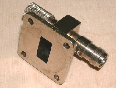
The disadvantages mentioned above can be overcome with waveguides. These are metallic tubes with round or angular cross-sections that are constructed in such a way that waves of specific wavelengths propagate in them at the speed of light. In waveguides, only those frequencies can propagate that are in a certain relation to the dimensions of the waveguide. The condition is that the wavelengths are smaller than the cut-off wavelength, which in the case of rectangular waveguides is twice the length of the wider waveguide side.
Wave motion in the waveguide
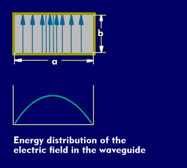
Physically, these are transverse waves( TEM) whose electric and magnetic fields are perpendicular to each other. The electric field (E-field) builds up between the two wider waveguide walls, the magnetic field (H-field) between the two narrower ones. The electric field is strongest in the center of the waveguide and decreases towards the walls. It changes with frequency and has maxima and minima in the longitudinal direction of the waveguide at intervals of half the wavelength. The attenuation is strongly dependent on the dimensions of the waveguides, which are specified in their dimensions according to DIN 47302. The wider waveguide side (a) always has twice the value of the narrower one (b). For example, if the a value is 19.05 mm, then the b value is 9.53 mm. The corresponding frequency band for this waveguide is between 9.84 GHz and 15.0 GHz.

The DIN specifications and designations correspond to those of IEC 153.
The RF signals are fed in and out of the waveguide via slots, funnels or holes.
Waveguides have several advantages over coaxial cables or microstrips. They are completely shielded against radiation, can transmit extreme peak powers, and have negligible loss when transmitting microwaves. Waveguides are used in transmitters and radar systems, in microwave ovens and in LNB converters, low- noise block converters (LNBs) used in parabolic antennas and for satellite reception.